
Source: Theo Mayer, “Observation Balloons,” World War I Centennial News Podcast, 2013; and Thomas Paone, “Protecting the Beaches with Balloons: D-Day and the 320th Barrage Balloon Battalion,” National Air and Space Museum, 4 June 2019.
How Long Has This Been a Problem?
Reliance on petroleum fuel has been woven into both historical and current U.S. policy and still affects military supply and operations today. In 1980, the U.S. government adopted the single fuel concept (SFC) to simplify logistics in limiting the distribution of ground and aircraft fuel to select petroleum fuel types.17 The SFC sought to optimize legacy liquid logistics into four types of petroleum fuel: JP-5, JP-8, F-24, and F-76.18 An unseen negative consequence of the SFC was tying combustion engine technology production and oil production in a vicious loop, as an end unto itself. As confirmed in a 2018 DOD manual, military logistics continues to be short-sighted with a narrow scope on petroleum.19 The DOD announced the use of alternative fuel, but this was limited to liquid petroleum with additization at best, negating hydrogen and other renewable or alternate energy sources that ultimately show policy as a barrier to reduce risk.20
Additionally, the legal basis, roles, missions, and organization of the U.S. military is outlined in a cohesive document of the U.S. Code under section Title 10. Title 10 has an entire chapter devoted to energy security. It recognizes the traditional renewable energy sources of solar, wind, biomass, and hydroelectric power, as well as tidal, wave, and current energy. Its goal for fiscal year 2025 is “to produce or procure not less than 25 percent of the total quantity of facility energy it consumes within its facilities” from renewable sources.21 Although largely focused on military bases and stations, Title 10 opens a positive way forward for the introduction of renewable energy with a military application. Moreover, the DOD has published an Operational Energy Strategy, which manifests its dedication to reduce tactical risk through energy diversification. The strategy highlights the pursuit of “renewable energy opportunities at contingency bases that harvest energy at the point of use to minimize the burden of resupplying operational forces with liquid fuel.”22
In 2010, the Marine Corps developed a nested policy in its expeditionary energy strategy. General James F. Amos, then-Commandant of the Marine Corps, outlined the price of legacy logistics and offered an overhaul solution demanding full institutional change: “By 2025 we will deploy Marine Expeditionary Forces that can maneuver from the sea and sustain . . . in place; the only liquid fuel needed will be for mobility systems.”23 Moreover, the Marine Corps Expeditionary Energy Office (E2O) was created to promulgate these policies into tactical existence. The E2O “works closely with the combat and technology development communities and serves as the proponent for expeditionary energy in the force development process to create a more lethal force that goes farther and stays longer on every gallon of fuel or every kilowatt it requires.”24
During a 2017 congressional hearing for nomination as U.S. secretary of defense, retired Marine Corps general James N. Mattis was asked what he would do to unleash the DOD from the tether of fuel. Mattis stated that the DOD’s “acquisition process should explore alternate and renewable energy sources that are reliable, cost effective, and can relieve the dependence of deployed forces on vulnerable fuel supply chains to better enable our primary mission to win in conflict.”25 His sentiments echo the aforementioned risks associated with legacy liquid logistics, as well as the promising solution that renewable energy provides as an alternative to sustaining forces in combat. Ultimately, nothing suggests that the Joint force is obsolete and mired in the past better than its dependency on fossil fuels. Though the SFC hinders progress beyond petroleum, Title 10 of the U.S. Code, DOD policy supported by its Operational Energy Strategy, and Marine Corps policy buttressed by its E2O manifest all recognize renewable energy as a force multiplier to enhance military lethality.
Factors Surrounding the Problem
Building on a foundation of history and policy related to military logistics, this study will now transition to the core problem of sustaining Marines in an EABO environment. Factors surrounding this problem include the physical environment of EABO, the MLR tasked with executing EABO, and how the Marine Corps plans to sustain future operations. EABOs are a tactic that hearkens back to the period between the world wars (1918–39), during which Marines trained in advanced base operations, seizing and holding key maritime terrain in support of the U.S. naval fleet. As seen in figure 4, EABOs are simply Marines operating on islands or in littoral zones to enable the greater naval fleet campaign. Marine Corps doctrine defines EABO as a “form of expeditionary warfare that involve the employment of mobile, low-signature, persistent, and relatively easy to maintain and sustain naval expeditionary forces from a series of austere, temporary locations ashore or inshore within a contested or potentially contested maritime area in order to conduct sea denial, support sea control, or enable fleet sustainment.” 26
As stated, EABOs require Marines to persist in austere environments within an adversary’s WEZ, making resupplies more difficult, which thereby creates an opportunity to change technology use or method of resupply. Renewable energy offers a way for deployed Marine units to become far more logistically self-sufficient, removing the onerous burden of frequent petroleum resupplies in operating environments that may not always boast friendly maritime or air superiority. Logistics is an operational art at the operational level, tying in strategic resupplies and tactical combat service support. EABOs are a sound concept that simply requires refinement due to difficult logistical realities.
Figure 4. The MLR in an EABO environment delivering fires on adversary vessels
Source: Tentative Manual for Expeditionary Advanced Base Operations (Washington, DC: Headquarters Marine Corps, 2019), 8–10.
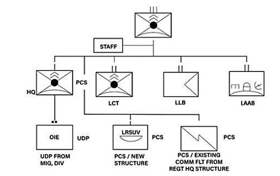
The Marine force charged with carrying out the EABO task set is the MLR. This unit is a new Marine formation that resulted from Force Design 2030 to better manage human resources and refocus the Marine Corps on its maritime roots in support of the Navy.27 As seen in figure 5, the MLR consists of a headquarters staff, a littoral combat team, a littoral antiair battalion, and a littoral logistics battalion. As the Marine Corps’ stand-in force, this formation will execute EABO by conducting sea control, sea denial, or fleet sustainment tactics with 1,800–2,200 Marines and sailors.28 Specific to the thesis of this study is the concept that MHK energy can provide an alternative to petroleum in supporting generators for COCs and light and ultralight hybrid tactical vehicles of the MLR. An analysis of the current MLR table of organization and equipment reveals 30 ultralight Polaris MRZR all-terrain tactical vehicles, 78 Oshkosh Joint Light Tactical Vehicles (JLTV), and four battalion-size COCs, as well as 124 SPACES and 2 GREENS solar systems29 This equipment set denotes the current reliance of the Marine Corps’ most expeditionary force on petroleum. This study will endeavor to link the use of MHK technologies as a potential solution to cut the tether of legacy liquid logistics and provide the logistical sustainment demanded by General Berger for successful EABO. The incorporation of renewable energy into a new Marine Corps operating concept is a vision into the future that regards innovation as key to future success in war.
Figure 5. MLR task organization
Source: Tentative Manual for Expeditionary Advanced Base Operations (Washington, DC: Headquarters Marine Corps, 2019), A-1.
The final factor surrounding the present petroleum problem is the Marine Corps strategy to sustain Marine forces operating within the littorals. Energy—or more broadly, logistics—is the pacing warfighting function for the Marine Corps, with fuel as the pacing commodity.30 The purpose of military logistics is to extend operational reach, increase endurance, and enable freedom of action. Noting the vulnerabilities associated with resupplying the MLR within an adversary’s WEZ during EABO, the Marine Corps developed a “spider web of sustainment” to create greater flexibility and redundancy.31 This layered logistical support plan leverages multiple regional nodes, vessels, and other means to provide forward forces with supply support options. Without continued sustainment of combat power in contested environments, the MLR will fail to support fleet operations. Adding to the spider web sustainment model, the office of the Deputy Commandant of the Marine Corps for Installation and Logistics developed a concept of global logistics awareness (GLA). This concept will use an integrated system of logistics including amphibious ships, Maritime Prepositioning Force (MPF) ships, caches, regional bases, and Joint service agreements to connect supply nodes with sensors, data, and networking capabilities.32 GLA logistical linkages will create a common supply picture and theoretically allow for a better push-and-pull system to resupply forward forces in need. Moreover, as General Berger noted, “Staying small also means radically reducing fuel consumption, which requires aggressive exploration of electric vehicles [and] alternative fuels.”33 Though the Marine Corps recognizes the challenges and vulnerabilities surrounding resupplies of the MLR during EABO, their efforts using GLA as a spiderweb sustainment model only optimize an antiquated process while neglecting the promise of creating self-sustainment through the use of renewable energy.
Considerations for Renewable Transition
The military’s problem of overreliance on petroleum for the conduct of operations tied to required resupplies is not presently in an urgent state that demands immediate reform. Military operations and sustainment will continue, even for the MLR during EABO. However, there remains a current financial cost, as well as a risk to force and risk to mission, associated with legacy liquid logistics.
As an organization, the DOD is the leading consumer of legacy liquid logistics in the world. In 2019, the DOD “spent over $12 billion to procure nearly 4.2 billion gallons of fuel for military,” rising at a rate of 1.5 percent annually.34 In the world market, the Organization of the Petroleum Exporting Countries (OPEC) regulates crude oil supply and ultimately sets prices. During the oil shocks of the 1970s, OPEC cut oil production and limited exports in protest of U.S. support for Israel during the Yom Kippur War (1973), highlighting the United States’ reliance on foreign oil. Domestic gas prices in the United States rose from $0.25 per gallon in 1973 to $1.42 per gallon in 1981, and have since reached more than $4.25 per gallon in 2022, with an additional OPEC planned cut of 2 percent in oil supply to boost global costs.35 Production is not currently limited, but both rising cost and rising demand pose future challenges to the U.S. military in general and the Marine Corps in particular, with its unofficial mandate to do more with less. In fiscal year 2020, the DOD purchased approximately 88 million barrels of fuel, with the U.S. Department of the Navy accounting for 26 million barrels, or 30 percent of the total, of which the Marine Corps consumed 5 million barrels.36
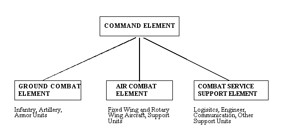
Figure 6. Marine air-ground task force (MAGTF) unit organizational chart
Source: U.S. Navy Seanet System, accessed 28 August 2023.
Within the Marine air-ground task force (MAGTF), the aviation combat element and its aircraft are responsible for 75 percent of all Marine Corps fuel consumption. This study offers a focus on renewable energy solutions that are tied to trimming excess fuel usage from generators, COCs, and light and ultralight hybrid tactical vehicles that affect the MAGTF’s command element, ground combat element, and logistics combat element. This limited scope of renewable energy application facilitates a test period and a phased implementation approach that allows the aviation combat element to continue to conduct fuel-based operations. Finally, another MAGTF, the Marine expeditionary unit (MEU), is estimated to consume more than 1 million gallons of fuel in a five-day period.37 This example stresses the importance of already proven fuel consumption and resupply requirements that may be applicable to the MLR. Though shielded from price volatility by purchasing fuel from the Defense Logistics Agency (DLA), the DOD is still subject to large surpluses and deficits in its working capital fund as a result of shifting fuel requirements. This further complicates the problem of fuel reliance.
In addition to the financial cost of legacy liquid logistics, petroleum resupplies are vulnerable and create risk to forces. Moving logistical ships or vehicle convoys inside a combat zone to resupply troops is inherently dangerous and risks the lives of servicemembers. Adversary forces target these critical vulnerabilities to more efficiently destabilize main effort centers of gravity during periods of armed conflict. During World War II, for instance, “merchant mariners had the highest casualty rate compared to any of the other services, and modern warfare underscores similar risks with Iraq and Afghanistan convoy deaths accountings for the majority of casualties.”38 While full resupply risk mitigation is highly unlikely, renewable energy offers an option to reduce the frequency of required resupplies by making forward forces more self-sustaining.
Beyond financial costs and risk to forces, traditional sustainment also presents a risk to mission due to friendly force reliance on petroleum. Without petroleum, tactical air and ground operations would slow and eventually cease. As mentioned in the introduction of this article, the U.S. military has invested in a wide array of tactical systems that use the combustion engine and therefore require petroleum fuel to operate. What does traditional sustainment look like? Figure 7 depicts the targets related to sustaining the force. On the ground, large trucks and trailers maneuver fuel from a major logistical node to the point of need. The logistical base, the route, and the convoy or truck within are all vulnerable targets. The fuel is conventionally brought into the combat zone by way of a large fuel tanker vessel, which presents a slow and vulnerable target. The key to sustaining operations ashore are traditional large fuel bladders. While highly capable of storing massive amounts of fuel, these bladders become heavy, static, and immovable targets once filled to capacity. Modern warfare considerations do not assume traditional air or maritime superiority, both of which are required conditions to move logistics in and within a combat zone at an acceptably low level of risk.
Figure 7. Marine Corps fuel trailer (left), MPF oiler (center), and fuel bladder (right)

Source: Sgt Ian Leones, “Maintenance Work,” Marines.mil, 19 July 2016; “Tankers,” U.S. Navy’s Military Sealift Command, accessed 28 August 2023; and Sgt Brandon Hubbard, USA, “Fuel to Fight: Inspector General and Fuelers Have Special Mission in ISIS Fight,” U.S. Central Command, 3 January 2017.
The current state of the U.S. military’s petroleum reliance problem has been shown to be threefold in an exponentially growing literal cost, a risk to forces, and a risk to mission. War always requires resources, and fuel is critical to sustaining operations today. Specifically for the Marine Corps, the MLR requires fuel to move firing assets within littoral areas during EABO to achieve sea denial or sea control. Though dependent on fuel itself, the MLR has the potential to expand its mission sets to complicate an adversary’s similar use of fuel by seizing key terrain such as advanced depots. If nothing is done about the problem of petroleum reliance, the Marine forces in EABO environments will ultimately remain vulnerable to required resupplies of precious petroleum for key equipment operations. Marine Corps major Andrew C. Eckert summarized the risk succinctly when he wrote, “Because of years of optimizing energy chain efficiency, the challenge is that the current concept for fulfilling energy needs was not developed to mitigate the vulnerabilities inherent in the contested maritime environment.”39 Though the Marine Corps recognizes the fundamental risks associated with fuel reliance, it has not yet fully addressed those risks, and it should consider the self-sustaining potential of renewable energy.
Application of the Solution
Overview of the Solution
A review of other successful renewable energy solutions will set conditions for understanding a potential military application of renewable energy technologies. Examining wind, solar, kinetic, and hydrogen power as renewable energy solutions, as well as nuclear power as an alternative energy solution, will generate an understanding of what has already been accomplished in this field.
Renewable energy sources provide a supplement to legacy liquid logistics and an alternative solution to supporting Marine forces in an EABO environment, creating self-sustaining forces that require less frequent resupplies. Specifically, MHK energy, a form of hydroelectric energy, is most suitable for Marine Corps use in island or littoral zones during EABO, as it captures tidal or wave mechanical energy as a potential power generation for the MLR. MHK energy is best postured to support ground tactical equipment, specifically COCs and light and ultralight hybrid tactical vehicles, while phasing in this new technology and methodology. Better understating lessons learned, positive outcomes, challenges, and constraints related to other renewable or alternate energy solutions will shape the military application of MHK energy to best sustain Marine forces in EABO environments.
Wind Power
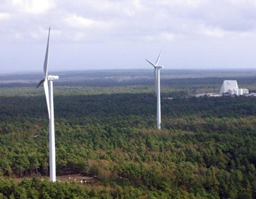
In accordance with the aforementioned Title 10 and DOD energy policies, wind power offers a promising renewable energy solution. Wind power contributes to clean energy through reduction of fossil fuel use and the ability to harness natural mechanical energy that is converted into electric energy. As seen in figure 8, a U.S. Air Force base in Cape Cod, Massachusetts, houses two windmill turbines that are capable of producing up to 1.5 megawatts of energy each and reduce energy costs by $1.5 million annually.40 One advantage of wind power is its prolonged harvesting time, especially when compared to the short 5–6 hours a day that are optimal for sunlight collection for solar power generation. A further consideration for wind power is the necessary minimum of 8 mile-per-hour winds for turbine generation capacity, with 25–36 mile-per-hour winds as ideal for maximizing turbine generation.41 Simply put, wind turbines are more permanent in nature and not expeditionary for field use, and not every military base or station lends itself to ideal wind speed ranges. Additional drawbacks to wind turbines include their tall infrastructure, which can act as an obstruction near air bases, as well as reported interference with radar systems. For all of the benefits of wind power as a renewable energy solution, there are many disadvantages and considerations that tie it to military bases and preclude it from use in the field.
Figure 8. U.S. Air Force wind turbines in Cape Cod, MA
Source: Lea Johnson, “Cape Cod Wind Turbines Help Air Force to Top DOD Energy Goals.” AirForce.mil, 9 October 2012.
Solar Power
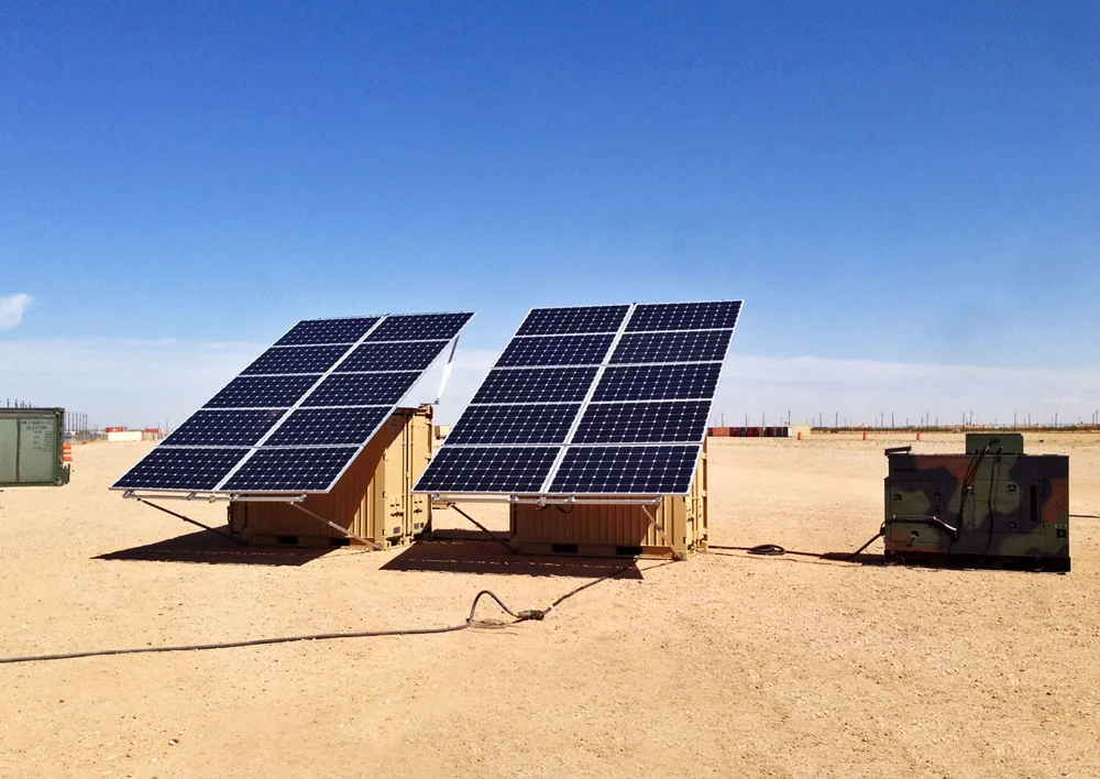
The opening background to this study briefly covered the application of solar power at military bases and stations through substantial stationary solar farms at MCAGCC Twentynine Palms, as well as the portable power of the GREENS and SPACES solar systems. As one of the few natural resources abundant for the MLR during EABO in an island or littoral zone, solar power has grand potential to support forward forces. The Scorpion Energy Hunter, as seen in figure 9, is an example of an already field-tested solar energy converter. Though larger than the SPACES and GREENS systems, the Scorpion is highly capable and remains expeditionary with consolidation into two quadcon shipping container units. This system “harvests solar energy, using the most advanced adjustable solar panels to convert sunlight into an energy output of 20 kilowatts . . . or storage capacity of 105 kilowatt hours.”42 It has the ability to power one COC and would complement the MLR’s limited capacity of only two GREENS systems.
Figure 9. Scorpion Energy Hunter solar power converter
Source: “Scorpion Energy Hunter,” MilSpray, accessed 28 August 2023.
Kinetic Energy
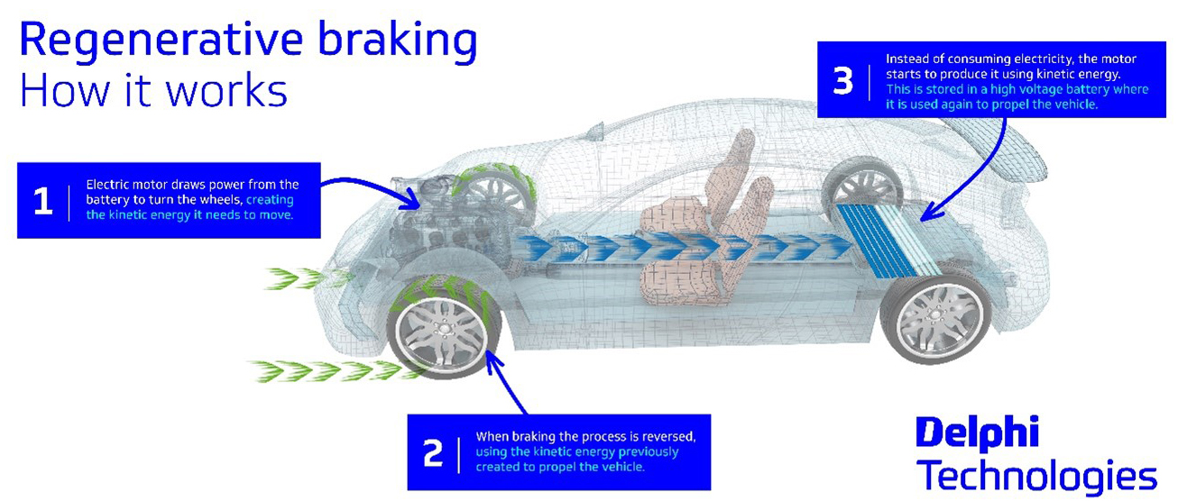
A less common form of renewable energy is kinetic energy, or the ability to transfer physical mechanical energy, movement, or motion into usable electrical energy. Kinetic energy has the capacity to be used in tandem with MHK energy, specifically in supporting light and ultralight hybrid tactical vehicles through regenerative braking. According to a Military.com article, “When the driver applies the brakes, the electric motor turns into a generator, and the magnetic drag slows the vehicle down.” Regenerative brakes “capture energy and turn it into electricity to charge the battery that provides power to an electric motor.”43 MHK energy would primarily recharge tactical vehicles, and it would rely on regenerative braking for subsequent on-the-move charging. After conducting operations, light and ultralight hybrid tactical vehicles equipped with regenerative braking could extend their range without required resupply by harnessing kinetic energy.
Figure 10. Regenerative braking process
Source: “Regenerative Braking Explained,” Delphi Technologies, accessed 28 August 2023.
Hydrogen
Hydrogen is a natural resource that exists in the form of an abundant gas. The commercial sector has already invested in hydrogen generators, cars, and plans for airliners by 2035.44 The advantages of hydrogen are numerous. It is safer than legacy liquid logistics, with a compressed tank puncture venting vertically and potential ignition being far less hazardous than petroleum.45 It is 50 percent more efficient than traditional engines and has a lower thermal and acoustic signature. Moreover, the energy derived from 1 pound of hydrogen is comparable to that of 16 pounds of batteries.46 As seen in figure 11, in 2017 the U.S. Army began working with the General Motors automotive company to develop and field test a hydrogen-powered Chevrolet Colorado ZH2 fuel cell electric vehicle.47 Further, in 2018 the Massachusetts Institute of Technology discovered that the raw metal of “aluminum could be ‘activated’ or prevented from rusting if it was heated in the presence of very small amounts of gallium and indium, metals anyone can purchase online. This created a safe and efficient means of generating hydrogen on demand.”48 This monumental discovery would allow the MLR to simply and safely produce its own hydrogen gas at the forward edge, making it even more self-sustaining. The main drawback to hydrogen is its nascent stage for modern military application, especially when compared to the combustion engine equipment already in operation. Additionally, a consideration for the military tactical use of hydrogen is the supply chain—specifically, in both the transport of compressed hydrogen systems and the safeguards therein, as well as the acquisition and transport of aluminum, gallium, and indium from a factory to the field for warfighter use at the point of need.
Figure 11. Hydrogen-powered Chevrolet Colorado ZH2

Source: Stephen Edelstein, “Military Hydrogen-Powered Chevy Colorado ZH2 Launches,” Green Car Reports, 4 October 2016.
Nuclear Energy
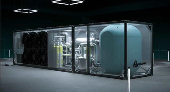
The inability of nuclear energy to regenerate precludes it from a renewable energy classification, and though potent, it produces an exponential energy output relative to other sources. The U.S. Navy recognizes the potential of nuclear power as an alternate energy source, as evidenced by its fielding of 66 nuclear-powered submarines in comparison to its 18 diesel-powered submarines that are kept in reserve.49 Military application of nuclear power is not limited to the maritime domain. Former SpaceX engineers at a new company called Radiant recently developed a “portable nuclear zero-emissions power source. Radiant claims its micro reactor can operate for up to eight years without refueling, power the equivalent of 1,000 homes, and fit into a shipping container.”50 Though nuclear power produces a large physical and heat signature, this microreactor is highly mobile and expeditionary. Radiant’s ability to put eight years’ worth of power into a container offers MLR forces a self-sustainment option during EABO and opens nuclear power to future research for land-based military applications.
Figure 12. Radiant’s nuclear microreactor
Source: “Radiant Products and Services,” Radiant Nuclear, 9 August 2022.
Table 1 highlights the MLR’s power requirements for its 4 COCs, 30 ultralight tactical vehicles, and 78 light tactical vehicles. The total MLR power requirement per day, depending on the frequency of use, is 2,840 kilowatts, or 2.9 megawatts, of energy. Considering that the MLR rates two GREENS systems to power two of its four battalion COCs, the adjusted demand would be 2,800 kilowatts, or 2.8 megawatts. Analysis of the MLR’s energy needs with comparative civil renewable energy systems reveals that a 2.8-megawatt power requirement for the MLR is both a positive and manageable energy end state.51 Further, this partial transition to renewable energy systems will reduce the MLR’s fuel dependency by roughly 30 percent, not including its boat company, unmanned aerial systems, generators for radars, or littoral logistics battalion requirements.
Table 1. MLR power requirements
|
Type
|
Quantity
|
Power requirement
|
Total
|
|
COC
|
4
|
20 kW
|
80 kW
|
|
MRZR (ultralight)
|
30
|
14 kW
|
420 kW
|
|
JLTV (light)
|
78
|
30 kW
|
2,340 kW
|
|
Total
|
|
|
2,840 kW (2.9 MW)
|
Source: courtesy of the author, adapted by MCUP.
Introducing Marine Hydrokinetic Options
The concept of MHK energy use involves harnessing the natural mechanical energy produced on the surface of a body of water via waves or subsurface hydro energy produced by tidal currents and converting that energy into usable electrical power. MLRs operating in island or littoral zones during EABO are surrounded by water with great power potential. MHK energy offers a renewable energy solution to capture the plentiful surrounding power inherent in the waves and tides of an EABO environment. Compared to other renewable energy sources, MHK technology is less developed, leaving it in nascent stages, expensive, and untested for military application.
Wave Energy
Waves provide forward forces a near-endless supply of energy but pose a challenge to harnessing it. A reaction to strong winds or storms produces waves that grow as range increases, ultimately resulting in large swells out at sea or breaking waves near shallow water.52 Waves materialize constantly all over the globe, during both day and night, due to the distance of the Earth relative to the Moon and their respective gravitational pulls.53 Another advantage of wave energy is that the vastness of world’s ocean surface area ensures a resource rich environment. However, waves are by nature destructive, diffuse, and variable.54 Studies have shown that wave power “is greatest well offshore in deep water but, as the waves move into shallower water, friction with the sea bed and their tendency to break cause energy loss.”55 Produced by stormy winds, waves offer a strong MHK renewable energy solution, with caution and considerations given to their destructive and varying characteristics.
Tidal Energy
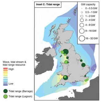
Tidal energy is more reliable and predictable than wave energy, albeit limited to the greatest power potential residing along coastlines. The gravitational relationship between the Sun, Earth, and Moon, as well as the bathymetry shape of the seabed, produce tides.56 Tides express a “periodic rise and fall of the water levels [that] gives rise to tidal currents.”57 The difference between the highest and lowest point in water level caused by the tide is known as range. As seen in figure 13, bathymetry—the measurement of ocean floor characters used to calculate currents, tides, and water temperatures—is a critical factor affecting tides and subsequent exploitation of harnessing currents for power generation. Specifically, tidal range and stream strength are much higher along an island and other coastlines when compared to open ocean. Tidal range devices are often integrated into onshore structures such as harbor walls. The preferred location for tidal stream turbines is approximately 1 kilometer offshore at a depth of 20–30 meters.58 Considerations for the employment of tidal energy devices include interaction with marine life, effect on the seabed and ecosystem, sediment transportation changes, undersea radar effects, and effects on fisherman. Tides have a reliable frequency, but they do not occur constantly over vast ranges when compared to waves. Further, “strong tidal streams do not accompany large tidal ranges. . . . Conversely, a relatively small tidal range may produce vigorous tidal stream through a narrow channel.”59 In other words, areas with a large rise and fall of water level do not correspond with a strong current from which to harness power, and a small rise and fall of water level does not equate to a slow and small tidal current. Finally, tides are docile, in opposition to the destructive nature of waves. Tides offer a strong MHK renewable energy solution with a comparatively passive nature, reliable frequency occurrence, and known but limited high range and stream strength along littoral coastlines.
Generally speaking, the Atlantic Ocean offers a greater tidal range, while the Pacific Ocean boasts larger waves. Ultimately, site selection in any theater will require vast data analysis coupled with confirmatory beach reports on maritime characteristics. MLR forces seeking to harness MHK tidal energy require a depth of knowledge in the proper site selection and employment as well as proper consideration given to the aforementioned associated challenges.
Figure 13. Tidal ranges in the United Kingdom
Source: Deborah Greaves and Gregorio Iglesias, eds., Wave and Tidal Energy (Hoboken, NJ: Wiley, 2018), 109, https://doi.org/10.1002/9781119014492.
Harnessing Tidal and Wave Energy
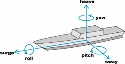
Understanding the devices used to harness tidal and wave energy, as well as power transfer, methods of employment, and related maritime terms, will provide a base for further exploration of tying MHK energy as a renewable energy source capable of supporting the MLR during EABO. Tidal energy converters (TEC) and wave energy converters (WEC) are devices that, when emplaced in a body of water, physically capture the kinetic energy of moving water as usable mechanical energy. This mechanical energy then goes into the power takeoff (PTO) unit, beginning “the process of converting mechanical energy into useable electricity via direct-drive, hydraulic, hydro, or pneumatic means.”60 As seen in figure 14, the ocean moves within 6 degrees of freedom, and corresponding WEC and TEC designs reflect movement direction to harness maritime energy. The six maritime movement characteristics are heave, surge, sway, pitch, roll, and yaw. These terms are defined in table 2.
Figure 14. Maritime movement characteristics
Source: “Wave Energy,” Liquid Grid, accessed 2022.
Table 2. Maritime movement definitions
|
Term
|
Definition
|
|
Heave
|
Vertical up-and-down movement
|
|
Surge
|
Horizontal movement parallel to wave direction
|
|
Sway
|
Horizontal movement perpendicular to wave direction
|
|
Pitch
|
Rotation about a horizontal axis causing front and back of device to oscillate up and down
|
|
Roll
|
Rotation about a horizontal axis causing device to rock from side to side
|
|
Yaw
|
Rotation about a vertical axis
|
Source: Paul A. Lynn, Electricity from Wave and Tide: An Introduction to Marine Energy (Hoboken, NJ: Wiley, 2013), 63–64, https://doi.org/10.1002/9781118701669.
There are many considerations when it comes to the siting of tidal and wave energy systems. Three general categories comprise the location placement of TEC and WEC devices, to include onshore, nearshore, or offshore. Onshore devices are fixed to a structure ashore; nearshore devices are attached to the ocean floor slightly offshore; and offshore devices are placed in the open ocean, where they are subjected to severe conditions, albeit with higher energy possibilities.61
An analysis of the different WEC and TEC devices will comprise the next section of this study. Reviewing the advantages, disadvantages, and considerations for the employment of these devices will inform readers of the potential military application for MHK energy to support MLR forces during EABO. The six main WEC devices are point absorbers, floating, oscillating water surge, submerged pressure differential, overtopping terminator, and attenuators. The six main TEC devices are crossflow turbines, horizontal axis turbine, vertical axis turbines, oscillating hydrofoil, tidal lagoon, and tidal barrage.
Wave Energy Converter 1: Point Absorber
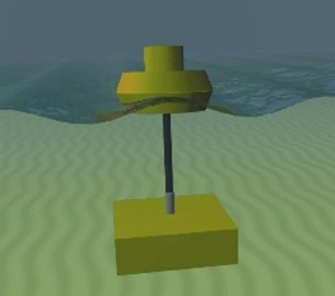
The first WEC is a point absorber, a heaving device. Point absorbers are small and produce power regardless of wave direction.62 Most point absorbers are a variation of a buoy, where one end moves vertically up and down across the peak and low point of each corresponding wave. According to the Liquid Grid, “The resulting reciprocating action is used to pump a fluid or drive a linear generator, which in turn can provide usable power.”63 To achieve full net vertical force, a point absorber’s design includes a float length that is smaller than a typical wavelength.64 The PowerBuoy is a premium point absorber device that boasts power production up to 11 megawatts as a buoy farm.65 However, the average individual WEC buoy produces 300 kilowatts each.
Figure 15. Point absorber
Source: “Wave Energy,” Liquid Grid, accessed 2022.
Wave Energy Converter 2: Floating Device
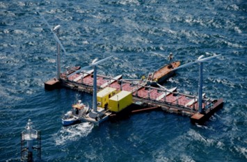
The second WEC is a floating device. As seen in figure 16, the Poseidon is a hybrid device with a floating foundation for multiple WECs as well as multiple wind turbines. As a WEC, the Poseidon has both an oscillating water column (OWC) device to trap air between surface water and an air turbine, as well as an oscillating apparatus that captures wave motion through physical flap arms. The 37-meter model includes 10 3-kilowatt WECs. Currently, WECs only produce 100–500 kilowatts, but the full-scale system will span 150 meters and produce 2.6 megawatts from the water columns.66 Importantly, this floating device shows flexibility.
Figure 16. Floating device
Source: Kaylie L. McTiernan and Krish Thiagarajan Sharman, “Review of Hybrid Offshore Wind and Wave Energy Systems,” Journal of Physics: Conference Series 1452 (2020): 5, https://doi.org/10.1088/1742-6596/1452/1/012016.
Wave Energy Converter 3: Oscillating Water Surge
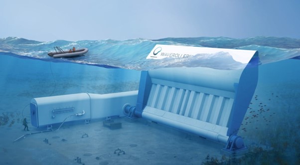
The third WEC is an oscillating wave or oscillating water surge (OWS) device. Employed in shallow waters and secured on the bottom of the ocean, these WECS use large flap arms to capture wave surge water movement. According to the Liquid Grid, “The movement of the flap acts like a large lever arm which can be mechanically linked to a generator to produce electricity or a pump to pressurize a fluid.”67 A prominent example of an OWS device is the WaveRoller. Employed in the nearshore area, up to 2 kilometers from the shore at depths up to 20 meters, the WaveRoller produces 350–1,000 kilowatts of power.68 As a comparison, similar oscillating water surge units produce approximately 800 kilowatts.
Figure 17. Oscillating water surge (WaveRoller)
Source: “Waveroller,” AW-Energy, accessed 2022.
Wave Energy Converter 4: Submerged Pressure Differential
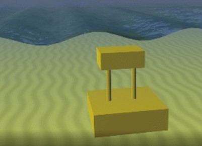
The fourth WEC is a submerged pressure differential (SPD) device. A fully submerged WEC anchored to the seabed, the SPD relies on upward and downward movement to generate power. There are two main types of SPDs: a pressure fluctuation device and a submerged point absorber. The first “relies on pressure fluctuations as a wave passes overhead to flex a pliable material such as [an] air bladder and squeeze a fluid to drive a turbine.”69 The WaveSwing by AWS Ocean Energy is a common pressure device that produces up to 80 kilowatts of power.70 The submerged point absorber generates power through the upward and downward movement of an underwater float that interacts with overhead waves. The CETO-5 is a conventional example of a submerged point absorber capable of 240 kilowatts of power production.71 SPDs offer survivability, harnessing destructive wave energy while safely undersea.
Figure 18. Submerged pressure differential
Source: “Wave Energy,” Liquid Grid, accessed 2022.
Wave Energy Converter 5: Overtopping Device
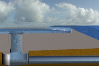
The fifth type of WEC is an overtopping or terminator device, which captures perpendicular wave energy. Long arms direct oncoming waves first toward the device and then up a ramp to a reservoir storage area above the mean sea level, where gravity drains it down back into the ocean through a turbine.72 In 2003, a one-fourth scale version of the WaveDragon, an overtopping device weighing 237 tons and spanning 58 meters, was field tested, noting a potential power achievement of 7 megawatts for the full-scale device.73 Overtopping devices are portable and boast easy installation, but their large size and high costs limit employment.74
Figure 19. Overtopping device
Source: “Wave Energy,” Liquid Grid, accessed 2022.
Wave Energy Converter 6: Attenuator
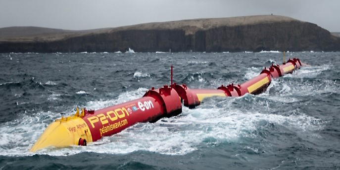
The sixth and final type of WEC is an attenuator. Attenuators are flexible floating WECs that are mounted parallel with respect to wave direction and employ heave, surge, and sway maritime movements to capture mechanical energy. A common example is the Pelamis, as seen in figure 20. Its snake-like design comprised of five sections allows it to capture energy along its length, “making its capture width much greater than its physical width.”75 The Pelamis boasts an omnidirectional ability to exponentially harness ocean energy where doubling its length would result in five times greater power capture. Reliable for up to 750 kilowatts of power production per section, the Pelamis went into administration in 2014.76
Figure 20. Attenuator (Pelamis)
Source: “Pelamis Wave Power,” European Marine Energy Centre, accessed 2022.
Tidal Energy Converter 1: Crossflow Turbine
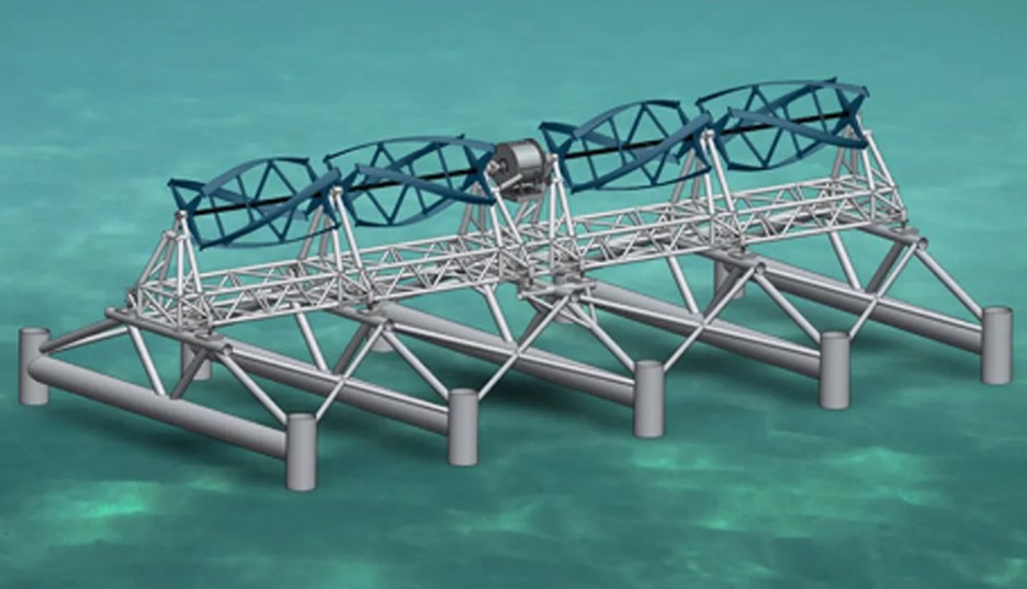
The first TEC is a crossflow turbine. The first four TECs reviewed in this sequence all use the tidal stream generation method of harnessing maritime power by placing a turbine within the tidal current flow. This TEC has a “large cylindrical mechanism composed of a central rotor surrounded by a ‘cage’ of blades arranged into a water wheel shape.”77 Water enters as a flat sheet, flowing over the blades creating torque as it moves to the turbine, hitting the blades once more as it leaves, again producing even more torque. Recently, a private company provided 180 kilowatts of power—enough to power 25 homes in the United States—from a crossflow turbine 30 meters off the coast of Maine.78 Though expensive and requiring expertise for installation, the crossflow turbine is scalable, survivable, and possess a self-cleaning feature due to input and output design functions.
Figure 21. Crossflow turbine
Source: Dave Levitan, “First Tidal Power in U.S. Starts Flowing to the Grid,” 18 September 2012.
Tidal Energy Converter 2: Horizontal Axis Tidal Turbine
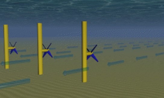
The second TEC is a horizontal axis tidal turbine (HATT). Like the crossflow turbine, the HATT uses tidal stream generation with a turbine that harnesses oncoming tidal current flow. HATTs are either permanently secured to the seabed, as seen in figure 22, or semipermanently weighed down on the sea floor with mooring as reinforcement. The HATT is the most common kind of TEC. They have a design comparable to windmill turbines, and due to water density being 800 times greater than air, a low current speed can still be useful.79 The MEYGEN HATT has “three blades with an 18-meter diameter, capable of rotating the turbine at each slack tide to face into subsequent ebb or flood tide, generating up to 1.5 megawatts of power each.80 Although semipermanent, the HATT requires massive lead times for planning and employment as well as incredible subject matter expertise to properly implement and maintain.
Figure 22. Horizontal axis tidal turbine
Source: “Wave Energy,” Liquid Grid, accessed 2022.
Tidal Energy Converter 3: Vertical Axis Tidal Turbine
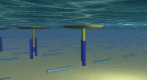
The third TEC is a vertical axis tidal turbine (VATT), which also uses tidal stream generation. VATTs maybe be employed as floating structures attached to moving platforms or permanently secured to a bridge or other structure placed within a tidal current path to harness maritime energy. The turbine is driven by vertically mounted blades that are capable of capturing current energy regardless of direction. VATTs are advantageous as they are “cheaper in production, and allow easier installation because the generator is on top, making it suitable for floating systems. Further, VATT design allows for more power extractions from tidal current than the HATT, for a higher coefficient of performance.”81 The GKinetic VATT is a moving boat-like platform that has underwater turbines capable of producing 1,000 kilowatts of power and, like other TECs, is scalable.82
Figure 23. Vertical axis tidal turbine
Source: “Wave Energy,” Liquid Grid, accessed 2022.
Tidal Energy Converter 4: Oscillating Hydrofoil
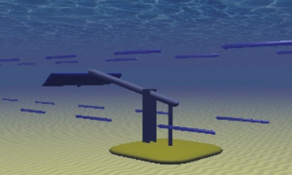
The fourth type of TEC is an oscillating hydrofoil or oscillating water surge (OWSC) device. Employing tidal stream generation, the OWSC design involves a flat foil at the end of an arm that corresponds to tidal pressure moving it upward and downward for power generation.83 Traditional HATT, VATT, and OWSC systems are subject to power extraction limits and require numerous devices to capture the surface area of oncoming tidal currents. A special OWSC, the undersea BeamReach, consists of 600 sail foils attached to two steel wires strung between two generators. This device is still in the testing phase but offers an inexpensive and efficient method of harnessing full-length tidal stream generation power.
Figure 24. Oscillating hydrofoil
Source: “Wave Energy,” Liquid Grid, accessed 2022.
Tidal Energy Converter 5: Tidal Lagoon
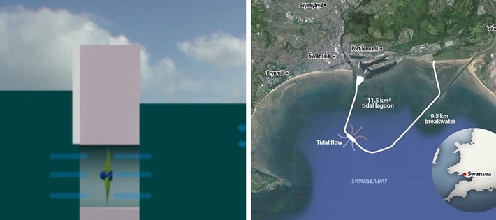
The fifth TEC is a tidal lagoon, which is a manmade structure that encloses a maritime area with a known high tidal range. Substantial amounts of water remain on the outside of the structure during a high tide. Water then releases into the lagoon through a narrow channel, where it passes over a turbine to generate power. Phil Smith writes that “this process also happens in reverse as the tide flows out (ebbs) because the turbines are ‘bi-directional’ and so electricity can be generated from the incoming and outgoing tides.”84 Purposeful in design, tidal lagoons can produce up to 320 megawatts of energy each.85 They are not suitable for supporting MLR forces in EABO environments, but they offer great power potential as a consideration for military bases and stations.
Figure 25. Tidal lagoon
Source: “Wave Energy,” Liquid Grid, accessed 2022.
Tidal Energy Converter 6: Tidal Barrage
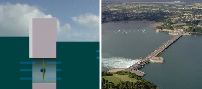
The sixth and final TEC is a tidal barrage. Tidal barrages, like tidal lagoons, do not use tidal stream generation or current surge strength. Rather, both tidal barrages and tidal lagoons use the range of high tide and low tides, much like a dam. When water is discharged from the high side to the low side, it passes through a slender channel along a turbine that spins and generates massive amounts of electricity. A tidal barrage structure differs from the tidal lagoon design in that it “spans an entire river estuary in a straight line.”86 Tidal barrages like the one in the Wyre estuary of England can produce up to 160 megawatts of electrical energy.87 Though capable of harnessing nearly all tidal range power potential, it is worth noting that these structures obstruct commercial maritime traffic and affect marine life as well.
Figure 26. Tidal barrage
Source: “Wave Energy,” Liquid Grid, accessed 2022.
Table 3. WEC and TEC power output summarization
|
Type
|
Device
|
Power output
|
Notes
|
|
Point absorber
|
Power buoy
|
300 kW–11 MW
|
Great potential employed as a farm. Simple, although best results offshore
|
|
Floating
|
Poseidon
|
500 kW–2.6 MW
|
Hybrid model, windmills, and OWC WEC.
|
|
Oscillating water surge
|
WaveRoller
|
800 kW–1,000 kW
|
Secured to seabed with marginal output.
|
|
Submerged pressure differential
|
CETO-5
|
80 kW–240 kW
|
Survivable, though a WEC employed undersea.
|
|
Overtopping terminator
|
WaveDragon
|
7 MW
|
Deployed at one-fourth scale, power potential is only an estimate.
|
|
Attenuator
|
Pelamis
|
750 kW–3.7 MW
|
Each section produces 750 kW. Decommissioned in 2014.
|
|
Crossflow turbine
|
TidGen
|
180 kW
|
Marginal output for undersea employment and complexity.
|
|
Horizontal axis tidal turbine
|
MEYGEN
|
1.5 MW
|
Massive, with large tonnage for gravitational mooring.
|
|
Vertical axis tidal turbine
|
Gkinetic
|
1,000 kW
|
May be employed on a platform, on a float with mooring, or by anchoring to a permanent structure.
|
|
Oscillating hydrofoil
|
Tidal Sail BeamReach
|
100 kW–6 MW
|
Still in testing phases.
|
|
Tidal lagoon
|
Swansea Bay, Wales
|
320 MW
|
Consideration for bases and stations, not field use.
|
|
Tidal barrage
|
Wyre Estuary, England
|
160 MW
|
Blocks entire river crossing.
|
Source: courtesy of the author, adapted by MCUP.
This section builds on those preceding that offer a deeper understanding of power through a discussion of maritime terminology and of the two pillars of MHK energy: tides and waves. A subsequent evaluation of the six primary WECs and six core TECs sets conditions to compare the power requirements of the MLR to the appropriate MHK renewable energy solution. Table 3 summarizes all MHK devices with respect to their power output and key considerations for employment. These civic renewable energy solutions are currently in commercial use and available for military application. MHK energy is a viable solution that offers real potential for supporting Marines as a cumulative part of the United States’ defense strategy. Given the national security implications tied to military dependency on fuel, the DOD should consider the advantages in operationalizing renewable energy. The time to act and innovate is now, if the United States is to be better postured for future war.
The next section outlines the challenges that the U.S. military must overcome to achieve successful MHK implementation, followed by a renewable energy concept of support for employment during EABO.
Challenges for MHK Renewable Energy Implementation
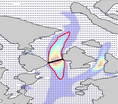
A primary problem for the employment of MHK wave and tidal energy converters by an MLR is site selection. That the MLR will be conducting EABO on unknown and unpredictable island or littoral zones further complicates an already difficult dilemma. The large surface area of the ocean offers premium power potential in the form of waves. As previously noted, wave energy is greatest offshore, and though waves dissipate energy as they approach the coastline, they remain a viable energy source at either location. MLR operations in the littorals makes harnessing deep sea swells less likely than nearshore waves. Further, whereas waves are plentiful, varied, and destructive, tides are comparatively docile with strong streams and high ranges. Figure 26 shows cooler colors as areas with low tidal power density (TPD) and warm colors as areas with high TPD. Of note, the black line between islands is approximately 2.5 kilometers long; therefore, the highest concentration of tidal stream energy exists some 4.5–6.5 kilometers offshore, which is less usable for an MLR application.
Figure 27. Tidal power density of Rosario Strait, WA
Source: Levi Kilcher, Robert Thresher, and Heidi Tinnesand, Marine Hydrokinetic Energy Site Identification and Ranking Methodology Part II: Tidal Energy (Washington, DC: National Renewable Energy Laboratory, 2016), 4.
The final consideration to site selection is depth. Levi Kilcher, Robert Thresher, and Heidi Tinnesand note that sites between 20 and 60 meters are “ideal” for tidal devices, while sites deeper than 150 meters are “too deep for economical tidal energy conversion.”88 The takeaway point from MHK site selection is that achieving optimal results is a purposeful science that requires prioritization and planning. The MLR does not currently have the luxuries of time or expertise. Further, since logistics does not drive operational decision making, energy site selection is an unlikely criterion for operational consideration. The criticality of the mission will be paramount and site selection secondary for the MLR during EABO. Therefore, an MHK WEC or TEC will need to be flexible, scalable, easy to employ, and efficient in multiple different littoral locations. Ultimately, proper employment of MHK systems will require a phased approach that is focused on developing the required subject matter expertise in renewable emplacement, operations and maintenance of renewable energy solutions.
The method of anchoring a WEC or TEC to the seabed offers a considerable challenge for MHK implementation. Securing both types of devices to a large permanent structure such as a bridge or tidal lagoon manifests the greatest power output results, but it introduces extensive costs in both time and money while offering little applicability to the MLR. Further, as seen in certain HATT devices, securing a gravitational seabed requires massive amounts of tonnage and subsequent specialty equipment for installation and retrieval. Moreover, nearly all WECs and TECs require mooring or anchoring. The three main types of mooring are passive, active, and reactive. As Madjid Karimirad et al. explain, “Passive mooring simply provides station keeping, while active mooring largely affects the power generation of the device itself, and reactive mooring links the converter to the PTO.”89 Whether employing a WEC or TEC, the MLR will require specialized equipment and expertise ranging from heavy equipment operation to Navy or Marine Corps dive teams for mooring.
An additional challenge to the employment of MHK systems is a limitation related to physics. The current design of both wind and maritime turbines cannot extract all of the power potential from flowing currents. The Betz limit describes a theoretical maximum coefficient for turbines, whereby only 59 percent of kinetic energy captured is convertible into usable energy.90 Notably, the VATT design facilitates a 64-percent energy capture.91 The inability of MHK devices to fully capture complete wave or tidal stream power potential due to design physics undoubtedly affects both the economy of force and return on investment.
Levelized cost of energy (LCOE) illustrates the expenses surrounding power production, including research and design, field testing, manufacturing, maintenance, and conversion. The LCOE of MHK devices is high when compared to mature examples of renewable energy in both solar and wind power. When wind was immature, the industry followed a strategy of “aggressive deployment in locations with favorable market conditions,” which ultimately resulted in “technological breakthroughs that lowered LCOE and thereby expanded the marketability of wind energy.”92 The U.S. military can accelerate the marketability of MHK energy through the adoption of tidal lagoon or tidal barrage technology at bases and stations in the near term, with a long-term focus on field testing TECs and WECs to assist in the sustainment of MLR forces in EABO environments.
A final challenge related to MHK employment is conversion and storage. Most MHK devices are located relatively close to a power grid, where complicated power conversion takes place. This is not suitable for military field use in an operational environment and would require additional step-down conversion equipment and more personnel for proper options, thereby bleeding combat power at the expense of remaining expeditionary. Further, should an MHK device produce more power than an MLR’s daily requirement, there would be a new logistical requirement to store that energy. This harvested energy would not only be economical for use of the MHK device but allow for a more rapid and ready resupply when needed. At its most base form, a battery farm could be employed to save the fully daily potential of captured energy. However, batteries are heavy, take up a large surface area, and would rely on limited rare earth materials should this solution be implemented in mass. Finally, the whole premise of military application of MHK technologies involves the conversion of maritime kinetic energy into usable electrical energy, which is contingent on military equipment being fully electric or hybrid. A viable MHK solution requires a ground tactical vehicle fleet that is hybrid electric at least and fully electric at best.
This study highlights five challenges to be considered in regard to military application of MHK technologies. Site selection, mooring, physics design limitations, LCOE, and power storage provide the foundation of important issues. Additionally, in line with Title 10 of the U.S. Code and DOD energy strategic policy, the Marine Corps’ expeditionary energy, water, and waste (E2W2) initial concept of operations document outlines four criteria that are considered important to the employment of new energy technology. Whether a renewable energy technology is agile, expeditionary, interoperable, and scalable make up the top Service standards for strategic employment of renewable energy technologies related to higher policy.93 These criteria, along with two others—cost and power output—comprise six total variables to objectively compare MHK TEC and WEC renewable energy devices for military application. All of the aforementioned qualitative data was empirically assigned a quantitative score ranging from 0 to 3, on a “simple low to high” or “not favorable to favorable” scaling system. Of note, the power criterion used here required an output of 1,000 kilowatts or greater to score a three, an output of 500–999 kilowatts to score a two, and anything below an output of 500 kilowatts to score a one. Table 4 displays the results.
Table 4. MHK comparison by Marine Corps E2W2 criteria
|
Type
|
Agile
|
Expeditionary
|
Interoperable
|
Scalable
|
Cost
|
Power
|
Total
|
|
Point absorber
|
3
|
3
|
2
|
3
|
3
|
2
|
16
|
|
Floating
|
3
|
3
|
2
|
2
|
2
|
2
|
14
|
|
Oscillating water surge
|
0
|
0
|
2
|
3
|
1
|
2
|
8
|
|
Submerged pressure differential
|
1
|
0
|
2
|
3
|
2
|
1
|
9
|
|
Overtopping terminator
|
1
|
2
|
2
|
3
|
1
|
3
|
12
|
|
Attenuator
|
3
|
2
|
2
|
3
|
3
|
3
|
16
|
|
Crossflow turbine
|
0
|
1
|
1
|
3
|
3
|
1
|
9
|
|
Horizontal axis tidal turbine
|
0
|
1
|
1
|
3
|
2
|
3
|
10
|
|
Vertical axis tidal turbine
|
0
|
1
|
1
|
3
|
2
|
3
|
10
|
|
Oscillating hydrofoil
|
0
|
1
|
1
|
3
|
3
|
3
|
11
|
|
Tidal lagoon
|
0
|
0
|
1
|
3
|
0
|
3
|
7
|
|
Tidal barrage
|
0
|
0
|
1
|
3
|
0
|
3
|
7
|
Source: courtesy of the author, adapted by MCUP.
After scoring each MHK device using the Marine Corps’ E2W2 criteria with an additional cost and power output component, the results were sorted by highest overall score. The results displayed in table 5 succinctly offer the reader an objective analysis of MHK devices and their suitability for military application specific to supporting MLR forces during EABO. Of note, although tidal devices generally produce exponentially larger power outputs than WECs, WECs scored higher on average than TECs due to their agility and expeditionary nature coupled with lower cost.
Table 5. Summarization of MHK device scores using Marine Corps criteria
|
Type
|
Total
|
|
Point absorber (WEC)
|
16
|
|
Attenuator (WEC)
|
16
|
|
Floating (WEC)
|
14
|
|
Overtopping terminator (WEC)
|
12
|
|
Oscillating hydrofoil (TEC)
|
11
|
|
Horizontal axis tidal turbine (TEC)
|
10
|
|
Vertical axis tidal turbine (TEC)
|
10
|
|
Submerged pressure differential (WEC)
|
9
|
|
Crossflow turbine (TEC)
|
9
|
|
Oscillating water surge (WEC)
|
8
|
|
Tidal lagoon (TEC)
|
7
|
|
Tidal barrage (TEC)
|
7
|
Source: courtesy of the author, adapted by MCUP.
Both tables 4 and 5 considered the MLR power requirements as depicted in table 1, compared against the MHK device’s output as seen in table 3, to determine the most overall efficient means.
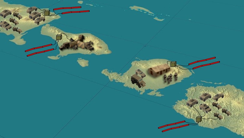
One of the two highest performing MHK devices was a WEC: the point absorber type most commonly employed as a power buoy. While noteworthy due to its simple design and ability to scale as a buoy farm, it lacks MLR applicability due to it achieving best results in swells far offshore. The other highest performing MHK device was another WEC: the attenuator or Pelamis five-sectioned snake. The attenuator harnesses wave energy out to sea or nearshore, producing 750 kilowatts per section, for a total of 3.7 megawatts. As a reminder, the MLR’s power requirement was based on energizing four battalion COCs, 30 ultralight tactical vehicles, and 78 light tactical vehicles totaling 2,840 kilowatts, or 2.9 megawatts Though this specific attenuator model is out of service, a similar model would more than meet the MLR’s power demands and boasts a simple design that is relatively easy to employ and maintain. Figure 28 illustrates a concept of MHK energy supporting a distributed MLR across multiple littoral zones. Specifically, the attenuator harnesses wave power and distributes it to the forward forces.
Figure 28. Concept of MHK energy supporting an MLR with the WEC attenuator device
Source: courtesy of the author.
The next highest performing MHK device was a floating WEC: the Poseidon. This is a hybrid device that uses an OWC WEC and wind turbine to produce 500 kilowatts of power but was scalable up to 2.6 megawatts. Though these systems are relatively easy to employ, the MLR’s power requirement would demand a minimum of two large platforms, thereby creating a substantial vulnerable logistical target.
Ultimately, every MHK device has strengths and limitations. However, the attenuator model is the most promising for military application specific to supporting the sustainment of MLR forces in EABO environments. As seen in figure 28, an attenuator device may be employed offshore in the vicinity of MLR forces to harness wave energy in support of COCs and light and ultralight hybrid tactical vehicles. That said, because the attenuator is a WEC, it is employed on the surface and is therefore targetable. Harkening back to the thesis statement of this article, renewable energies offer a supplement to fuel—not a replacement for fuel. MHK solutions provide military commanders with logistical options that are more redundant at the tactical level and negate operational level resupply frequency by way of increased self-sustainment.
Broader Implications
The MLR has subordinate battalions that are likely located in a minimum of four different positions, generating the need for multiple MHK systems at each. Though the attenuator WEC meets the MLR’s power requirements, the MLR will not be centrally located. Therefore, sustainment of distributed operations necessitates the use of multiple MHK devices, regardless of the selected type. Further, logistical redundancy requires several systems for operational continuity. The broader implication at the tactical level is the proven feasibility of MHK systems supporting the power requirements of the MLR, specifically its COCs and light and ultralight hybrid tactical vehicles. This relieves a majority of the requirement for the Marine Corps to send vulnerable resupply aircraft or ships within an adversary’s WEZ to resupply an MLR in an EABO environment, consequently mitigating risk to force as well as risk to mission. Further, if MHK systems are shown to physically support the requirements of limited tactical vehicles, then they also have the potential consequence of positively affecting other major end items. Renewable energy support to light and ultralight hybrid tactical vehicles would likely accelerate the move of medium and heavy tactical vehicle as well as other ground-based assault platforms from a petroleum system to a hybrid system or even a fully electrical system. Finally, proven MHK support to operational equipment in the field would make the employment of MHK technologies attractive to the DOD, specifically in the use of tidal lagoons and tidal barrages at military bases and stations to harness the same power potential at scale while saving money for operational reinvestment elsewhere. Though technology expansion is possible through testing and trials, renewable energy has the potential to streamline the levels of war. Logistics is an operational art that requires a tie to strategic assets feeding directly down to the tactical level that may otherwise be killed off, should renewable energy plant a positive self-sustaining solution. With renewable energy, the U.S. military can now elevate its focus from tactics to strategy.
Service-level change requires the Marine Corps to look across an established framework to wholistically consider the implications to doctrine, organization, training, materiel, leadership and education, personnel, facilities, and policy (DOTMLPF-P). A DOTMLPF-P analysis determines the approach to fill a functional gap.94 This material-focused solution of MHK devices supporting an MLR during EABO comes in response to a Service-wide shift. Specifically, the Commandants Planning Guidance of 2019 and Force Design 2030, as well as the Tentative Manual for Expeditionary Advanced Base Operations, called the Marine Corps back to its maritime roots in support of the greater naval fleet.95 General Berger argued, “While we are modernizing the Marine Corps using the pacing threat [China] as our benchmark, we . . . must still be capable of performing global crisis response operations.”96 Force Design 2030 removed tanks and minimized cannon artillery from the Marine Corps inventory, while standing up MLRs to execute expeditionary advanced base operations.
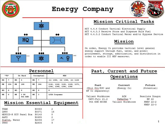
Though Force Design 2030 is a Service-level program, units at lower levels are seizing the initiative to preshape their tables of organization and equipment to support modern military tasking. For example, in the 3d Marine Logistics Group (3d MLG), reorganization and realignment efforts have harnessed the initiatives found in Force Design 2030 and display an organizational openness to change. As seen in figure 29, 3d MLG internally realigned a company from the 9th Engineer Support Battalion to directly under the headquarters of Combat Logistics Regiment 3. Energy Company now has a new home and a more modern name, though it lacks contemporary capabilities to match. Tasks for Energy Company include conducting tactical electrical supply; receiving, storing, and dispensing bulk fuel; and conducting tactical water services, all with the standard distribution of military occupational specialties. The realignment of Energy Company, while well-intentioned, simply moved around an already existing capability for a marginally more positive effect. To meet the demand of modern military problems, and to keep pace with the vision of Force Design 2030, all change needs to be purposeful. Talent Management 2030 argues that the Marine Corps can no longer change with incremental adjustments.97 Broader implications include making new units, such as Energy Company, capable of ushering in operational energy tasks such as the implementation of new renewable energy equipment, vice simply executing archaic fuel, water, and electrical tasks.
Figure 29. Energy Company, Combat Logistics Regiment 3, 3d Marine Logistics Group
Source: David Bunting, “Company Commander, Energy Company, Combat Logistics Regiment 3, 3d Marine Logistics Group, III Marine Expeditionary Force, Fleet Marine Force” (capabilities chart, internal document, 2022).
Creating a solely material-focused solution without allowing leadership to address the remaining DOTMLPF-P concerns negates a more effective implementation of renewable energy technologies. In June 2021, Chief Warrant Officer 5 Luc P. Brennan proposed a new Marine Corps military occupational specialty (MOS), 1320 Operational Energy Limited Duty Officer (LDO), with 1390 Bulk Fuel Officer and 1120 Utilities Officers serving as feeder specialties due to power generation expertise.98 Chief Warrant Officer 5 John Walter noted that the Operational Energy LDO would “act as the principal energy advisor to the Commander; coordinating energy requirements, account for usage, develops energy policy, identify energy risk and development of mitigation strategies, and direct energy implementation across the full range of military operation (ROMO) to extend the operational reach of current and future weapons systems.”99 Additional recommendations include adding energy as another subfunction of Marine Corps logistics and renaming classes of supply to reflect broader energy—specifically, changing Class III from a legacy liquid logistics term for petroleum, oil, and lubricants (POL) to operational energy, which encompasses POL and all other energy sources. These subtle changes will shift the paradigm of Marine Corps thinking from traditional to modern sustainment. As the Marine Corps continues to modernize the force to meet the demands outlined in Force Design 2030, remaining competitive requires a wholistic approach across DOTMLPF-P. Creating the Operational Energy LDO MOS will establish a Service-level stakeholder to usher in MHK systems as a viable solution for supporting MLR forces in an EABO environment.
Counterarguments and Accommodations and Refutations of Counterarguments
Currently, major military end items of planes, tanks, and trucks use combustion engines that require petroleum to operate and will be in service through 2050. Converting the power source engine from liquid fuel to a renewable energy source would create a great financial burden. The counterpoint of establishing common ground on the issue focuses on phasing in renewable energy technology and corresponding major end items. Specifically, the focus should first be on powering COCs and light and ultralight hybrid tactical vehicles to prove the worthiness of renewable energy in a military field application, and then on phasing in additional equipment as appropriate, acknowledging that some degree of fuel, repair parts, or other logistical resupply requirements will likely exist in perpetuity.
Converting fully to renewable energy will still result in vulnerabilities and logistical targets—albeit MHK devices as targets, vice fuel trucks, fuel bladders, and fuel tankers. The counterpoint is as follows. Yes, MHK WEC and TEC devices as well as other renewable energy technologies emit signatures and create targets just as traditional legacy logistics resupply methods do. However, renewable energy is more self-sustaining, and resolutions for renewable energy limitations will occur eventually. Renewable energy ultimately yields a lower resupply requirement than traditional sustainment. Being able to sustain oneself within an adversary’s WEZ, where maritime and air superiority is episodic at best, increases force protection and reduces the number of targets for the adversary. Further, as the LCOE becomes more economical, renewable energy technologies such as MHK systems become scalable for employment in mass to create redundancy and reduce risk to the mission if the renewable energy source is targeted. Finally, tidal energy converters are subsurface and more survivable.
The next argument is that solving the Class III(b) fuel problem by supplementing forces with an MHK renewable energy solution will alleviate resupply requirements of fuel but not those of class-one subsistence and other materials. Undoubtedly, those forces will still require food and water resupplies, but these could be accomplished through risk-mitigated delivery means including a high-off set Joint Precision Airdrop System (JPADS), with aircraft flying outside of the adversary’s WEZ capable of dropping supplies within the WEZ to friendly forces or unmanned subsurface vessels able to resupply class one forward. The JPADS or unmanned subsurface vessel resupply methods are relatively small and not conducive to massive fuel resupplies, but they provide an option for other types of resupplies. MHK energy in particular and renewable energy in general may solve the fuel problem, but the other classes of supply remain a requirement. As a result, logistics stands fast as the key function to warfare, both now and in the future.
Another argument covers the requirements for battery farms, backup batteries, and all major end items converted to hybrid or electric, should MHK systems be implemented. This renewable energy solution will require national access to, the processing of, and fielding of lithium and other rare-earth materials. Both petroleum and lithium are limited resources. This argument is very valid and requires more research noting current U.S. access to quantities of rare-earth materials needed to develop more batteries and hybrid systems. Further, additional comparative analysis specific to the cost of procuring lithium or the continuation of procuring petroleum is required with reasonable consideration to the growth or decline of the respective commercial energy sectors. Finally, while this argument challenges MHK energy as a renewable energy alternative to petroleum, the DOD should also research hydrogen as a renewable energy solution and nuclear as an alternate energy solution, both of which are capable of military field and base applications. Ultimately, acquiring limited resources for renewable energy use may optimize efficiencies in war but also create competition that points toward conflict.
Conclusion
Applicable to the entire U.S. military, this article addresses the problems that traditional sustainment poses for Marine forces requiring regular resupplies of legacy liquid logistics, which ultimately creates vulnerabilities tied to costs, risk to force, and risk to mission. MLR forces conducting EABO within an adversary’s WEZ exacerbate the problem of traditional sustainment, with episodic air and maritime superiority remaining an enduring requirement for the conduct of forward resupplies. This research argues positively for a military application of renewable energy that is capable of better enabling forward forces. Specifically, MHK energy technologies can provide an alternative, supplementary, and complementary source of energy to—but not a full replacement for—legacy liquid logistics, which will extend Marine endurance, in a forward, austere EABO environment, creating options to persist within an adversary’s WEZ and continue naval fleet support without being tied to regularly required resupplies. Further, renewable energy will be most effective in the near-term in supporting smaller-scale focused COCs and light and ultralight hybrid tactical vehicles to begin a phased approach focused on wave and tidal energy to create efficiency and redundancy while reducing risk. Renewable energy manifests a makeover in the operational art of logistics by providing a self-sustaining solution that better links the strategic and tactical levels of war as a supplementary option to commanders.
Ramifications of renewable energy technologies supporting an MLR in an EABO environment include cutting the tether of traditional sustainment, which ultimately creates a self-sustaining force that requires less frequent resupplies, thereby reducing risk to force and risk to mission. Specifically, MHK energy solutions can make forces self-sustaining with TECs or WECs that provide the energy requirements to power COCs as well as light and ultralight hybrid tactical vehicles. This study identified that the most efficient MHK device for military application is either the attenuator or point absorber WEC, reducing MLR power consumption requirement by 30 percent. Not without challenge, renewable energy technologies will require Service-wide investment and span across the spectrum of DOTMLPF-P, with an Operational Energy LDO to lead and advise. Other renewable energy sectors experienced their own takeoffs by aggressively deploying in market-rich condition areas, which resulted in the very technological breakthroughs that offer MHK technologies a similar potential for lowering operating costs to expand marketability. Further, the adoption of energy as a subfunction of logistics and the renaming of Class III from POL to operational energy will reframe the Marine Corps’ sustainment mindset and set conditions for a positive way ahead. Renewable energy technologies—specifically MHK devices have the power potential to positively affect ground equipment for an MLR in an EABO environment—can open the door for other military field and base applications. These civic renewable energy solutions are currently in commercial use and are available now for military application. Given the national security implications tied to military dependency on fuel, the DOD should consider leveraging renewable energy to enhance operational effectiveness in contested environments. The time to act and innovate is now, if the United States is to be better postured for future war.
Endnotes
- Gen David H. Berger, Force Design 2030 (Washington, DC: Headquarters Marine Corps, 2020), 10.
- “What Is Renewable Energy?,” United Nations Climate Action, accessed 28 August 2023.
- Matthew DeCarlo, Scientific Inquiry in Social Work (n.p.: Pressbooks, 2018).
- “U.S. Marines Take Lead in Deploying Clean Energy,” Pew Charitable Trusts, 21 April 2014.
- “Marine Corps Expeditionary Energy Office,” Marines.mil, accessed 28 August 2023.
- United Nations Conventions for the Laws of the Sea (1982).
- Nicola Jones, “The Ocean Is Hotter than Ever: What Happens Next?,” Nature, 10 May 2023.
- Enhancing Combat Capability: Mitigating Climate Risk, Department of Defense Budget [for] Fiscal Year (FY) 2024 (Washington, DC: Department of Defense, 2023).
- Donald W. Engels, Alexander the Great and the Logistics of the Macedonian Army (Berkeley, CA: University of California Press, 1978), 14, 23.
- Robert Goralski, and Russell W. Freeburg, Oil & War: How the Deadly Struggle for Fuel in World War II Meant Victory or Defeat (New York: Morrow, 1987; Quantico, VA: Marine Corps University Press, 2021), 185, https://doi.org/10.56686/9780160953613.
- C. N. Trueman. “Operation Blue,” History Learning Site, 15 May 2015.
- Goralski and Freeburg, Oil & War, 185–96.
- Learning, Marine Corps Doctrinal Publication 7 (Washington, DC: Headquarters Marine Corps, 2020), 2-14.
- “Air Balloons in the Civil War,” National Park Service, August 2021.
- “Balloons and Dirigibles in WWI,” National WWI Museum and Memorial, 2022.
- Roberta Blevins, “Barrage Balloons: The First Line of Defense against Enemy Aircraft,” Mommy Like Whoa (blog), 17 November 2022.
- Paul J. Kern et al., “An Albatross around the U.S. Military’s Neck: The Single Fuel Concept and the Future of Expeditionary Energy,” Modern War Institute at West Point, 29 June 2021.
- “Military Fuels and the Single Fuel Concept,” in NATO Logistics Handbook (Brussels: North Atlantic Treaty Organization, 1997).
- DOD Management of Energy Commodities: Overview, Department of Defense Manual 4140.25, vol. 1 (Washington, DC: Department of Defense, 2018).
- The Code of Federal Regulations defines additization as the process of adding detergent to gasoline to create detergent-additized gasoline. See “Electronic Code of Federal Regulations (e-CFR),” Legal Information Institute, Cornell Law School, accessed 27 October 2023.
- United States Code, Title 10, Chapter 173: Energy Security, Subchapter 1: Energy Security Activities §§ 2915.
- 2016 Operational Energy Strategy (Washington, DC: Department of Defense, 2016).
- Gen James F. Amos, Marine Corps Expeditionary Energy Strategy and Implementation Plan (Washington, DC: Headquarters Marine Corps, 2011).
- “Marine Corps Expeditionary Energy Office.”
- “Advance Policy Questions for James N. Mattis: Nominee to be Secretary of Defense,” U.S. Senate Committee on Armed Services, 2017.
- Tentative Manual for Expeditionary Advanced Base Operations, 2d ed. (Washington, DC: Headquarters Marine Corps, 2023), 1-3–1-4.
- Berger, Force Design 2030.
- “Marine Littoral Regiment (MLR),” Marines.mil, 11 January 2023.
- “Tables of Organization and Equipment,” Marine Corps Total Force Structure Management System, accessed 2022.
- Sustaining the Force in the 21st Century: A Functional Concept for Future Installations and Logistics Development (Washington, DC: Headquarters Marine Corps, 2019); and Capt Walker Mills and Erik Limpaecher, “Need Fuel?: Marines Should Make Moonshine Hydrogen,” U.S. Naval Institute Proceedings 147, no. 11 (November 2021).
- John Sattely and Jason A. Paredes, “Sustainment of the Stand-In Force,” War on the Rocks, 12 September 2022.
- Sustaining the Force in the 21st Century.
- Gen David H. Berger, “A Concept for Stand-In Forces,” U.S. Naval Institute Proceedings 147, no. 11 (November 2021).
- Walker Mills and Erik Limpaecher, “The Promise of Hydrogen: An Alternative Fuel at the Intersection of Climate Policy and Lethality,” Modern War Institute at West Point, 27 December 2021.
- “The Oil Shocks of the 1970s,” Energy History, Yale University, accessed 1 October 2022; Joseph Brusuelas, “That ’70s Show: Lessons from the Oil Shortages of Nearly 50 Years Ago,” Real Economy Blog, 24 March 2022; and “Opec: What Is It and What Is Happening to Oil Prices?,” BBC News, 5 October 2022.
- Michael Baskin and Konrad Gessler, “How Plummeting Fuel Prices and Reduced Operations Could Free up Billions of Defense Dollars,” War on the Rocks, 26 May 2020; and Marine Corps Expeditionary Energy Strategy and Implementation Plan.
- Maj Andrew C. Eckert, “Setting Conditions to Solve Problems: Making a Marine Corps that Can Build Resilient Energy Chains,” Marine Corps Gazette 104, no. 4 (April 2020): 13–17.
- Erik Limpaecher, “Secure Alternative Fuel Environment (SAFE) Concept: Fuel for Contested Logistics, in an Era of Climate Change Adaptation,” Naval Postgraduate School, 7 December 2021.
- Eckert, “Setting Conditions to Solve Problems,” 13.
- SMSgt David Byron, USAF, “New Wind Turbines Help Air Force Go Green,” AirForce.mil, 28 October 2011.
- SSA Jose O. Rivera-Rivera, “Could Wind or Solar Energy Replace Diesel for Aviation Ground Maintenance Operations?” (thesis, Marine Corps Command and Staff College, Marine Corps University, 2013).
- “Scorpion Energy Hunter,” MilSpray, accessed 28 August 2023.
- “Electric Vehicles and Regenerative Breaks,” Military.com, accessed 2022.
- Mills and Limpaecher, “The Promise of Hydrogen.”
- Mills and Limpaecher, “Need Fuel?”
- Limpaecher, “Secure Alternative Fuel Environment (SAFE) Concept.”
- Col Omar J. Randall, “An Untethered MLR: Supporting Stand-In Forces,” Marine Corps Gazette 106, no. 3 (March 2022): 37–43.
- Mills and Limpaecher, “Need Fuel?”
- “How Many Submarines Does the U.S. Navy Have?,” USS Kennedy Organization, 15 October 2022.
- Randall, “An Untethered MLR,” 38.
- For these calculations, see appendix 2.
- Paul A. Lynn, Electricity from Wave and Tide: An Introduction to Marine Energy (Hoboken, NJ: Wiley, 2013), 5, https://doi.org/10.1002/9781118701669.
- “What Causes Ocean Waves?,” National Oceanic and Atmospheric Administration (NOAA) Ocean Exploration, accessed 28 August 2023; and “Why Do Waves Get Stronger at Night?,” Vedantu, accessed 28 August 2023.
- Lynn, Electricity from Wave and Tide, 6.
- Lynn, Electricity from Wave and Tide, 9.
- Lynn, Electricity from Wave and Tide, 11, 15.
- Deborah Greaves and Gregorio Iglesias, eds., Wave and Tidal Energy (Hoboken, NJ: Wiley, 2018), 126, https://doi.org/10.1002/9781119014492.
- Greaves and Iglesias, Wave and Tidal Energy, 105, 126.
- Lynn, Electricity from Wave and Tide, 15.
- Ross Henderson, “Design, Simulation, and Testing of a Novel Hydraulic Power Take-Off System for the Pelamis Wave Energy Converter,” Renewable Energy 31, no. 2 (February 2006): 271–83, https://doi.org/10.1016/j.renene.2005.08.021.
- Donsheng Qiao et al., “Review of Wave Energy Converter and Design of Mooring System,” Sustainability 12, no. 19 (2020): 1–31, https://doi.org/10.3390/su12198251.
- Qiao et al.. “Review of Wave Energy Converter and Design of Mooring System,” 7.
- “Wave Energy,” Liquid Grid, accessed 2022.
- Lynn, Electricity from Wave and Tide, 64.
- Mohsen Fadaeenejad et al., “New Approaches in Harnessing Wave Energy: With Special Attention to Small Islands,” Renewable and Sustainable Energy Reviews 29 (January 2014): 345–54, https://doi.org/10.1016/j.rser.2013.08.077.
- Kaylie L. McTiernan and Krish Thiagarajan Sharman, “Review of Hybrid Offshore Wind and Wave Energy Systems,” Journal of Physics: Conference Series 1452 (2020): 5, https://doi.org/10.1088/1742-6596/1452/1/012016.
- “Wave Energy,” Liquid Grid, accessed 2022.
- “Waveroller,” AW-Energy, accessed 2022.
- “Wave Energy,” Liquid Grid, accessed 2022.
- “AWS Waveswing Trials Exceed Expectations,” AWS Ocean Energy, accessed 2022.
- Matt Williams, “Harnessing the Waves: The CETO Wave-Power Station,” HeroX, accessed 2022.
- “Wave Energy,” Liquid Grid, 2022.
- Lynn, Electricity from Wave and Tide, 207.
- Qiao et al., “Review of Wave Energy Converter and Design of Mooring System,” 9.
- Lynn, Electricity from Wave and Tide, 188.
- Greaves and Iglesias, Wave and Tidal Energy, 598.
- “Crossflow Turbine,” Energy Education, accessed 2022.
- Dave Levitan, “First Tidal Power in U.S. Starts Flowing to the Grid,” 18 September 2012.
- “Tidal Energy–Devices,” CityU School of Energy and Environment, Marine Energy Research, accessed 2022.
- “MEYGEN,” SAE Renewables, October 2022.
- Dendy Satrio, I Ketut Aria Pria Utama, and Mukhtasor Mukhtasor, “Vertical Axis Tidal Current Turbine: Advantages and Challenges Review,” Proceeding of Ocean, Mechanical and Aerospace–Science and Engineering 3 (November 2016).
- “Energy from Flow Acceleration,” GKinetic, accessed 2022.
- “Tidal Energy–Devices.”
- Phil Smith, “What Is a Tidal Lagoon?,” Tidal Lagoon Power, accessed 2022.
- James Ayre, “320 MW Swansea Bay Tidal Lagoon Project Moves Closer,” Clean Technica, 15 February 2014.
- Smith, “What Is a Tidal Lagoon?”
- Plamena Tisheva, “Atlantis Signs Heads of Terms for 160-MW Tidal Barrage Project Release,” Renewables Now, 21 November 2017.
- Levi Kilcher, Robert Thresher, and Heidi Tinnesand, Marine Hydrokinetic Energy Site Identification and Ranking Methodology Part II: Tidal Energy (Washington, DC: National Renewable Energy Laboratory, 2016), 9.
- Madjid Karimirad et al., “Applicability of Offshore Mooring and Foundation Technologies for Marine Renewable Energy (MRE) Device Arrays” (conference presentation, Renew2014: International Conference on Renewable Energies Offshore, Lisbon, Portugal, November 2014).
- Lynn, Electricity from Wave and Tide, 93.
- Javier Castillo, “Small-Scale Vertical Axis Wind Turbine Design” (thesis, Tampere University of Applied Sciences, 2011).
- Kilcher, Thresher, and Tinnesand, Marine Hydrokinetic Energy Site Identification and Ranking Methodology, 15.
- “Expeditionary Energy, Water, and Waste, Initial Capabilities Document,” Marines.mil, 2011.
- Department of Defense Dictionary of Military and Associated Terms, Joint Publication 1-02 (Washington, DC: Department of Defense, 2016), A-52.
- See Gen David H. Berger, Commandants Planning Guidance: 38th Commandant of the Marine Corps (Washington, DC: Headquarters Marine Corps, 2019); Berger, Force Design 2030; and Tentative Manual for Expeditionary Advanced Base Operations.
- Gen David H. Berger, Force Design 2030: Annual Update, May 2022 (Washington, DC: Headquarters Marine Corps, 2022), 4.
- Gen David H. Berger, Talent Management 2030 (Washington, DC: Headquarters Marine Corps, 2021).
- CWO5 Luc Brennan, “USMC Operational Energy Limited Duty Officer” (U.S. Marine Corps point paper, June 2021).
- CWO5 John Walter, “Naval Expeditionary Force Engineering” (U.S. Marine Corps initial planning team inputs, January 2022).